Site Assessment: Structural Load, Shading and Roof Condition
Every installation begins with a structural review, not a module order. A standard framed PV array adds roughly 12–20 kg/m² (2.5–4 lb/ft²) of dead load, while ballasted flat-roof systems can reach 40–80 kg/m² depending on wind zone. Designers must verify rafter spacing (16 in versus 24 in on-center changes rail spans and attachment counts dramatically), sheathing thickness, and the roof's remaining service life. Under ASCE 7-22 in the United States and EN 1991-1-3 in Europe, the PV array becomes a new dead load and a new surface for snow drift and wind uplift — both must be recalculated, not assumed.
Shading analysis comes next. A site survey with a Solmetric SunEye or fisheye-lens capture, later modeled in PVsyst or Aurora Solar, should confirm that annual shading losses stay below roughly 5–10 percent. Because modern half-cut modules with three bypass diodes lose only a third of their output when partially shaded, module-level power electronics are often unnecessary — but chimneys, dormers and adjacent trees still dictate string boundaries. Designers should map the irradiance profile hour by hour rather than relying on a single "shaded / unshaded" judgment.
Finally, roof condition and geometry. A PV system is a 25–30 year commitment, and as a rule of thumb, any roof covering within ten years of its expected end of life should be replaced before mounting hardware goes down. Orientation and tilt matter too: a 30–35° pitch facing true south is optimal across most of the mid-latitudes, but east-west ballast layouts can pack 15–25 percent more capacity onto the same roof at roughly 85–90 percent of the specific yield. Selecting the right [solar panels](/products/solar-panels) — 425–440 W half-cut monocrystalline TOPCon units are now mainstream — sets the physical envelope for everything that follows.
Mounting Systems: Rails, Attachments and Waterproofing
The mounting structure is where most long-term failures originate. On composition shingle roofs, the standard approach is a flashed attachment plate lag-bolted into rafters with two 5/16 in stainless fasteners, sealed with a butyl or EPDM gasket and an aluminum flashing plate that tucks under the course above — sealant alone is never the primary waterproofing layer. Tile roofs require tile hooks with careful replacement of broken tiles, and standing-seam metal roofs use non-penetrating clamps that grip the seam directly, eliminating roof penetrations entirely. Rails are typically 6063-T5 aluminum extrusion, sized from span tables that account for snow and wind loads.
Waterproofing discipline follows NRCA and manufacturer guidelines: ice-and-water shield in cold climates, correct flashing overlap sequence (upper courses over lower), and no fasteners below the waterline of the roof plane. On flat membranes — TPO, EPDM, modified bitumen — designers choose between ballasted, adhered, or mechanically attached systems; ballast is cheapest but adds significant dead load and requires parapet height checks.
Wind uplift governs the engineering. ASCE 7-22's components-and-cladding provisions create corner and edge zones where uplift pressures can be two to three times the field-of-roof value, so attachment density must increase at perimeters. Modules themselves must be IEC 61215 certified to at least 2,400 Pa front and rear load, with 5,400 Pa ratings recommended for snow regions. Clamping position matters — portrait mounting typically allows clamps at the quarter points, while orientation often forces longer rails and closer clamp spacing.
Electrical Design: Strings, Voltage Windows and Rapid Shutdown
String sizing is arithmetic with real consequences. Installers must calculate Voc at the record low ambient temperature using the module's temperature coefficient — for a typical TOPCon module with Voc of 38.9 V and βVoc of −0.25%/°C, a 10-module string at −10 °C reaches about 417 V, comfortably inside a 600 V residential limit but requiring re-checking at −20 °C in northern climates. The MPPT window must simultaneously accommodate Vmp at high cell temperatures (often 65–70 °C), where string voltage sags. Getting this wrong either clips energy or destroys inverters.
Conductor sizing follows NEC 690.8's 125 percent continuous-current factor on both Isc and inverter output, with voltage drop targets below 2 percent on the DC side and 1.5 percent on AC. Connectors must be listed and matched — mismatched MC4 brands are a known source of series arc faults. NEC 690.11 requires arc-fault circuit interruption, and 690.12 requires rapid shutdown: conductors within 1 ft of the array boundary must drop to 30 V within 30 seconds of initiation. Europe's equivalent framework is IEC 62548, which addresses array design, string protection and isolation.
Grounding and bonding (NEC 690.43) demand listed lugs, star washers and a continuous equipment grounding conductor, or listed grounding clips rated for the rail system. Every one of these calculations belongs in the permit package; jurisdictions from California to Queensland now reject applications with incomplete string calculations.
Inverter Architecture, Storage and Grid Interconnection
Inverter selection drives the array's electrical topology. String inverters offer 98 percent-plus CEC efficiency at the lowest cost per watt; microinverters and DC optimizers add module-level monitoring and shade tolerance at a 15–30 cent/W premium. DC/AC ratio — typically 1.1 to 1.3 — is a deliberate economic trade: slight clipping at peak irradiance is cheaper than oversizing the inverter. Modern [inverters](/tech/inverters) also provide grid-support functions mandated by IEEE 1547-2018 and UL 1741 SB, including volt-var and frequency-watt response.
Storage integration is increasingly standard. DC-coupled architectures charge a battery directly from the array through a hybrid inverter, avoiding double conversion losses; AC-coupled systems retrofit more easily. LFP chemistry dominates residential storage with 90–95 percent round-trip efficiency and 6,000–10,000 cycle ratings, and typical residential sizing of 5–13.5 kWh supports self-consumption rates of 60–70 percent in markets like Germany and Australia. Choosing a matched [battery storage](/tech/battery-storage) system at design stage is far cheaper than retrofitting later.
Interconnection is the final gate. Net metering, feed-in tariffs and export limits vary enormously: some German regions cap export at 70 percent of installed capacity, while several Australian networks impose 5 kW per-phase export limits. Applications must be filed with the distribution network operator before energization, and smart-inverter settings configured to local grid codes.
Installation Sequence, Safety and Commissioning Tests
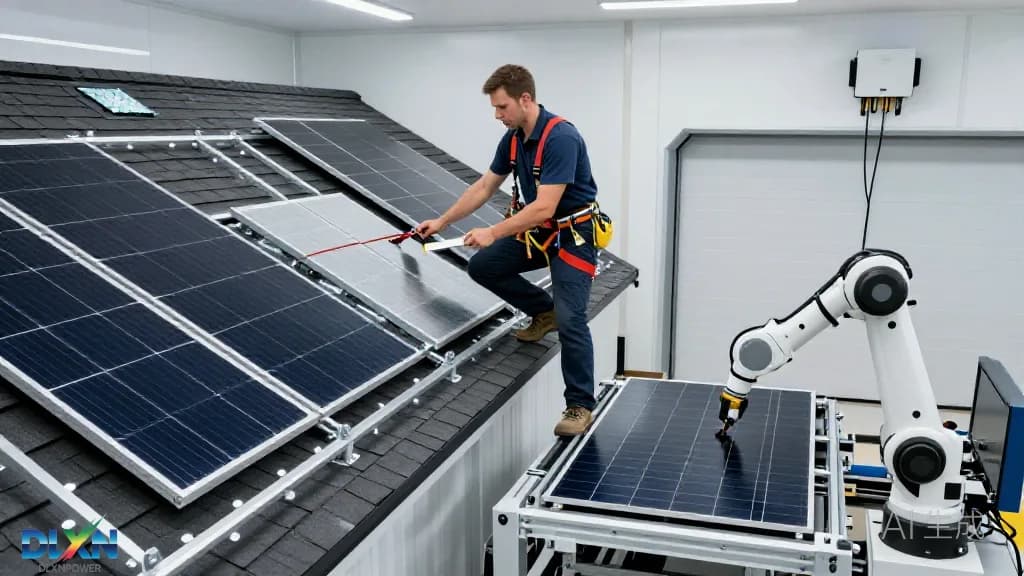
A residential crew of two can typically complete a 6–10 kW system in one to two days: mounting hardware on day one, modules and wiring on day two, commissioning on the morning of day three. Fall protection is non-negotiable under OSHA 1926.501 or local equivalents — roof anchors, 100 percent tie-off, and edge protection where parapets are absent. Material staging and load distribution matter too; stacking 25 kg modules in one roof area can temporarily exceed point-load limits.
Commissioning should follow IEC 62446-1, the international standard for PV system documentation and verification. The required test sequence includes visual inspection, continuity and polarity checks, insulation resistance testing at 1,000 V (acceptance threshold typically ≥1 MΩ), open-circuit voltage and short-circuit current comparison against expected values, and — increasingly — I-V curve tracing and infrared thermography under irradiance of at least 400 W/m² to catch cell-level defects and connector hotspots.
Documentation closes the loop: as-built single-line diagrams, string layouts, equipment labels at the main service panel, warranty registrations, and a monitoring baseline captured on the first clear-sky day. Regulators and insurers increasingly require this package, and it materially simplifies future service calls.
Monitoring, Degradation and Lifetime Economics
Once energized, performance should be tracked against a modeled baseline. A healthy residential system typically delivers a performance ratio of 0.75–0.85 and a specific yield of 1,000–1,600 kWh per kWp depending on latitude and climate. Monitoring platforms reporting at 15-minute intervals reveal string-level anomalies — a single failed bypass diode or a loose connector will show as a persistent 5–10 percent deviation long before it becomes a fire risk.
Maintenance is modest but not zero. Soiling losses run 1–5 percent annually in temperate climates and considerably higher in arid or agricultural regions; cleaning frequency should follow measured data rather than assumption. Annual visual inspection, torque checks on bonding hardware, and thermographic surveys every two to three years are best practice. Module degradation of 0.4–0.55 percent per year is now standard for TOPCon products, backed by 25–30 year performance warranties.
The economics have shifted decisively. According to BloombergNEF, mainline TOPCon module prices fell below $0.10/W in 2024, and NREL's cost benchmark series puts U.S. residential installed costs at roughly $2.70–3.00/Wdc — with balance-of-system and labor now dominating the cost stack. The IEA's Renewables 2024 report notes that solar PV supplied around three-quarters of global renewable capacity additions, and rooftop systems represent a large share of distributed build-out, with Australia alone exceeding 3.9 million small-scale installations. Reviewing [completed projects](/projects) across comparable climates and roof types remains the fastest way to sanity-check a design before construction begins.