
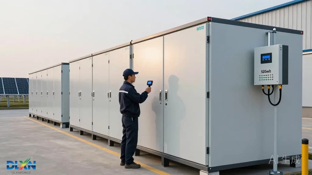
Why Round-Trip Efficiency Is the New Battleground for Commercial Storage
Round-trip efficiency (RTE) is no longer a cell-level specification. In commercial systems it is measured at the AC terminals and includes the power conversion system (PCS), transformer, thermal management, controls, and standby loads. A lithium iron phosphate (LFP) cell may convert 95–97% of energy in controlled DC tests, but a full cabinet can lose another 5–8 points to inverters, auxiliaries, and part-load operation. According to NREL’s 2024 Annual Technology Baseline, utility-scale lithium-ion BESS RTE typically sits at 86–88%; commercial systems now reach 92%. The shift is visible across [battery storage systems](/tech/battery-storage) designed for behind-the-meter duty.
The market context makes every point material. The IEA’s Batteries and Secure Energy Transitions report notes global battery storage capacity reached 90 GW in 2023 and must scale to 1,200 GW by 2030. BloombergNEF’s 2H 2024 Energy Storage Outlook projected 69 GW/169 GWh of global additions in 2024. As deployments scale, RTE becomes a direct driver of levelized cost of storage (LCOS). For a 1 MW/4 MWh commercial system cycling once per day, moving from 85% to 92% RTE increases delivered energy by roughly 102 MWh per year—about $15,300 at $0.15/kWh.
The Technical Levers Behind the 92% Round-Trip Milestone
The first lever is cell and pack chemistry. Modern LFP cells achieve coulombic efficiency above 99.5% and DC energy efficiency of 95–97%, with 6,000–12,000 cycles depending on depth of discharge and temperature. Thinner foils, electrolyte additives, and laser-welded busbars reduce internal resistance. At pack level, shorter busbars, lower-contact-resistance connectors, and integrated cell-to-pack designs cut ohmic losses. DLXN’s [lithium battery products](/products/lithium-battery) illustrate how pack-level design choices—cell spacing, thermal plates, and welded interconnects—translate into system-level efficiency rather than datasheet-only cell performance.
The second lever is power electronics. Silicon-carbide (SiC) MOSFETs are replacing silicon IGBTs in commercial PCS units, raising peak conversion efficiency from roughly 98% to 99% and, more importantly, holding efficiency at part load. A three-level ANPC topology reduces switching losses and harmonic distortion. At the same time, DC-coupled solar-plus-storage architectures eliminate one AC–DC conversion when PV energy charges the battery. Liquid cooling reduces auxiliary fan energy, and AI-based energy management systems (EMS) state of charge (SOC), coolant setpoints, and dispatch. The breakthrough is the stacking of these gains, not a single miracle component.
Silicon Carbide and DC-Coupling: Where the Losses Disappear
SiC power conversion is the most visible hardware change. In a conventional 100–500 kW commercial PCS, switching losses and conduction losses can consume 1.5–2.5% in each direction. SiC devices switch faster with lower on-resistance, allowing smaller filters and higher efficiency across the 20–100% load band. DLXN’s [inverter technology](/tech/inverters) approach focuses on this part-load behavior, because commercial loads rarely operate at continuous nameplate. A PCS that holds 98.5% efficiency at 30% load can outperform a 99% peak-efficiency unit that collapses at low load.
DC coupling changes the energy path in solar-plus-storage projects. In an AC-coupled design, PV DC power is inverted to AC, then rectified back to DC to charge the battery—two conversions. A DC-coupled system sends PV power directly to the battery DC bus, saving 2–4 percentage points on the solar-to-battery path. Tesla’s Megapack 2 XL datasheet lists 92% round-trip efficiency at the AC terminals; Sungrow’s PowerTitan 2.0 liquid-cooled system claims system RTE above 90%; Fluence’s Gridstack Pro targets over 90% for large commercial and utility projects. These are not laboratory cells; they are containerized products.
The caveat is that DC coupling is not universally superior. AC-coupled systems offer more flexible siting, easier PV expansion, and independent operation of PV and storage. The efficiency advantage depends on the share of PV energy that charges the battery and the dispatch profile. For grid-charged commercial arbitrage, the DC path offers no benefit. Buyers should require RTE quoted at the AC terminals, at a defined C-rate, ambient temperature, and auxiliary load—not a DC-only number.
Thermal Management and AI Dispatch Add Several More Points
Thermal management is an underappreciated efficiency lever. Air-cooled battery cabinets often consume 3–8% of throughput in fan and HVAC energy, especially in hot climates; liquid-cooled systems can cut auxiliary consumption to 1–3% while holding cell-to-cell temperature deltas below 3°C. Lower temperature deltas reduce internal resistance and slow calendar degradation. Safety standards such as UL 9540A and NFPA 855 drive designers toward modular, liquid-cooled enclosures with isolated compartments—designs that also happen to be more efficient.
AI-driven EMS adds another 5–10% in usable energy by forecasting site load, PV output, and tariff windows, then optimizing SOC and coolant setpoints. Rather than charging to 100% and holding, the EMS can shift charging to cooler hours, avoid high-C-rate excursions, and reserve capacity for demand-charge peaks. IEEE 1547-2018 requires voltage and frequency ride-through, while IEEE 2030.5 governs communications; grid-forming inverters add capability but can introduce conversion losses if not tuned. Efficiency and grid support must be co-.
Degradation is the long-run efficiency story. A system that starts at 92% RTE may fall to 88–89% after several thousand cycles as internal resistance rises. AI dispatch that avoids high SOC at high temperature can slow that decline. Warranty structures increasingly specify throughput in MWh rather than years, which aligns the operator and manufacturer around efficiency retention. For commercial buyers, the relevant metric is not “92% today” but “90% after 6,000 cycles and 10 years.”
Commercial Economics: What a 7-Point Efficiency Gain Is Worth
Lazard’s LCOS v8.0 (2024) puts utility-scale standalone storage at roughly $124–$338/MWh and commercial behind-the-meter storage at roughly $199–$426/MWh, depending on duration, interconnection, and market. Efficiency improvements push toward the lower end by increasing delivered energy per installed megawatt-hour and reducing augmentation. A 7-point RTE gain on a 4 MWh system delivers about 102 MWh more per year; over a 10-year life, that is roughly 1,020 MWh, or $153,000 at $0.15/kWh before degradation and discounting.
The value is larger where demand charges are high. In markets such as California, Massachusetts, and New York, commercial demand charges can exceed $20/kW-month. A 1 MW system that discharges efficiently during a 15-minute peak can save $20,000 per month in demand charges alone, and higher RTE reduces the energy needed to replenish the battery. DLXN’s [commercial projects](/projects) show how RTE, dispatch, and tariff design interact; the best projects combine storage with PV and fast, efficient inverters rather than treating efficiency as a standalone specification.
Deployment Reality: Standards, Degradation and Bankability
Efficiency claims must survive commissioning. UL 9540A testing addresses thermal runaway propagation, NFPA 855 sets installation requirements, and IEEE 1547-2018 governs interconnection. None of these standards directly certifies RTE, so buyers need contractual test protocols: AC-to-AC RTE at 25°C and 40°C, at 0.5C and 1C, including HVAC, controls, and transformer losses. Independent performance testing—often using power analyzers and calibrated meters—should be part of the commissioning plan, not an afterthought.
The bankable metric is warranted throughput. A 92% RTE system with a 10-year, 25 GWh throughput warranty is more valuable than a 93% claim without augmentation terms. Ask for degradation curves, augmentation schedules, EMS cybersecurity documentation, and spare-parts commitments. DLXN’s [contact](/contact) team can help translate datasheet efficiency into a procurement specification that matches the site’s load profile. The efficiency breakthrough is real, but it only becomes an economic breakthrough when it is measured, warranted, and dispatched correctly.