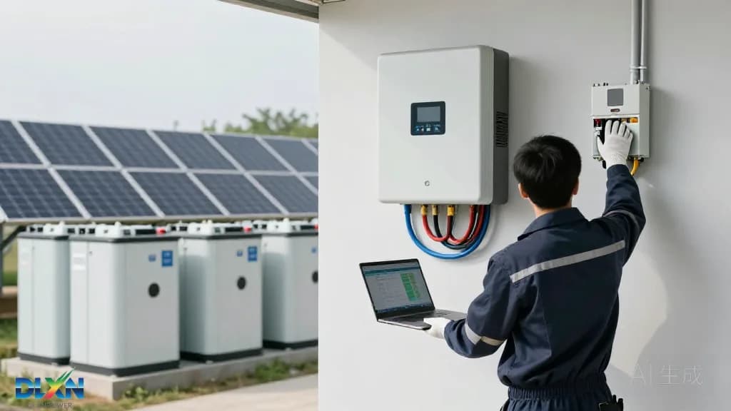
Sizing the Hybrid Inverter to Array and Battery
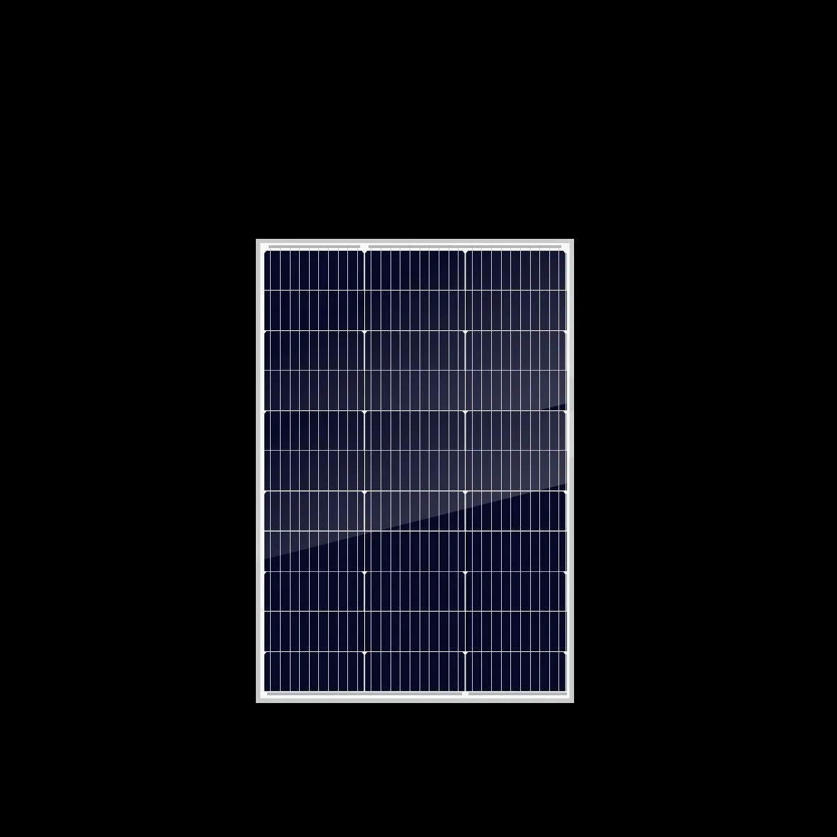
The first decision is continuous AC output rating. Most residential hybrid inverters sit between 3 kW and 12 kW, and the DC/AC ratio should land between 1.1 and 1.3 to capture clipping losses without wasting module capacity. NREL's residential benchmarking work shows that systems with ratios above 1.4 gain very little additional annual yield in most US climates, while inverters run hotter and clip more in summer. For a 6 kW array of high-efficiency [solar panels](/products/solar-panels), a 5 kW hybrid inverter is a typical, well-balanced pairing.
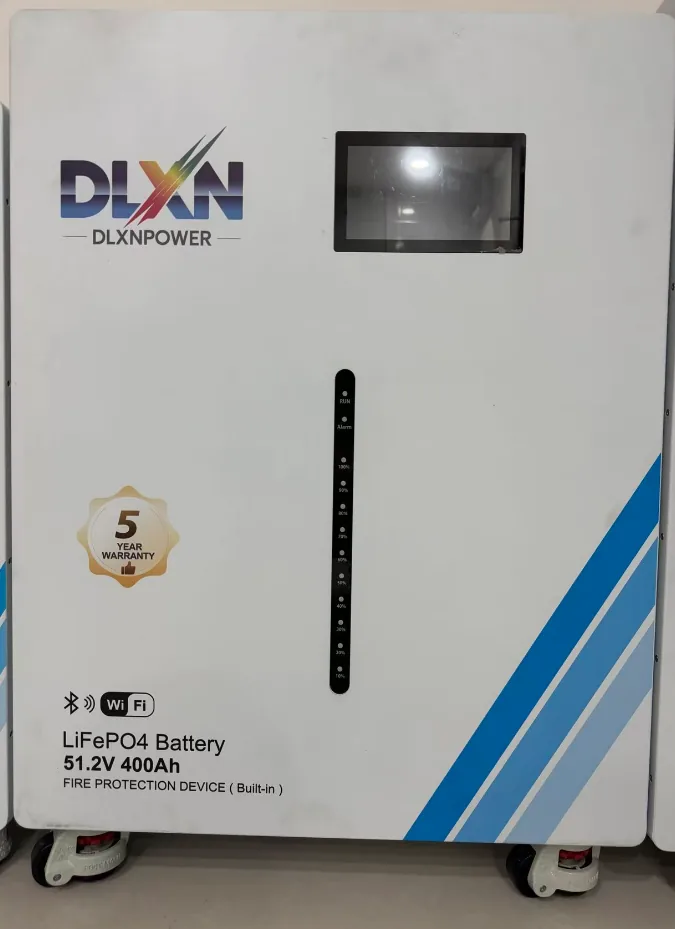
The battery port rating is a separate and often overlooked constraint. A 10 kWh lithium iron phosphate (LFP) pack rated at 0.5C can accept 5 kW of charge and deliver roughly 5 kW continuously; if the inverter's battery port is limited to 4 kW, that becomes the ceiling regardless of pack capability. Always compare the inverter's maximum charge and discharge current against the battery's datasheet, not against marketing capacity.
Surge handling matters as much as steady-state numbers. Motor loads such as well pumps, compressors and air handlers draw three to five times rated current for a second or more. A 5 kW inverter with a 10 kW surge rating for five seconds handles most residential backup panels, but a 4 kW unit with a 1.5× surge rating will trip. Map every circuit on the backup sub-panel before finalizing the inverter model.
DC-Coupled Hybrid vs AC-Coupled Retrofit
Architecture choice usually follows the project type. New-build systems should default to a DC-coupled hybrid, where PV strings and battery share a single high-efficiency conversion stage. Peak MPPT efficiency on premium hybrids reaches 97.5–98.5%, and Euro-weighted efficiency typically sits near 97%. Because the battery charges directly from the DC bus, no second inversion step occurs, preserving roughly 5–8% of round-trip energy compared with an AC-coupled topology.
AC-coupled retrofits make sense when an existing string inverter is healthy and under warranty. The battery inverter — often a multi-mode unit — is added on the AC side, leaving the PV system untouched. The advantage is resilience: if the storage inverter fails, the PV system keeps producing. The penalty is double conversion, which costs 3–5% of round-trip efficiency and requires careful AC bus and panel capacity planning.
Whichever route you choose, verify transfer time. Backup-capable units typically switch in 10–20 ms, which is fine for lighting and electronics but may reset sensitive servers. For those loads, an online double-conversion UPS or a unit with sub-4 ms transfer is the correct specification. Review options in our [inverter technology overview](/tech/inverters) before locking the design.
Battery Voltage, Chemistry and C-Rate Matching
The 48 V versus high-voltage debate is really a current-versus-compatibility trade-off. At 48 V nominal, a 5 kW discharge draws about 104 A, requiring 35 mm² cable and careful lug torque; at 400 V, the same power draws only 12.5 A. High-voltage architectures (100–500 V) therefore suit larger systems and longer cable runs, but they generally require a manufacturer-matched battery and closed-loop CAN communication with the inverter.
Chemistry choices are now dominated by LFP. Typical LFP cells deliver 6,000 cycles to 80% state of health, excellent thermal stability and 90–95% round-trip efficiency, and BloombergNEF's storage cost surveys show pack prices continuing to fall through 2024–2025. Nickel-manganese-cobalt packs offer higher energy density but are increasingly rare in stationary home storage. Our [battery storage technology](/tech/battery-storage) pages detail the trade-offs.
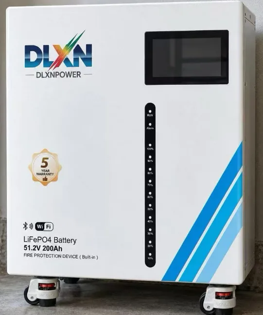
C-rate discipline protects the investment. If a 10.24 kWh pack (200 Ah at 51.2 V) specifies a 50 A maximum continuous charge current, set the inverter's charge limit accordingly — do not leave it at the factory default of 100 A. Similarly, verify the discharge limit against the backup loads. A conservative 0.3–0.5C operating window will typically extend service life beyond the datasheet's rated cycle count.
Siting, Thermal Management and Derating
Inverter output is rated at 25°C ambient, and nearly every residential unit begins derating between 40°C and 45°C. Manufacturers' datasheets publish derating curves; a 5 kW unit mounted in a sun-exposed garage in Phoenix may deliver only 4.2 kW on a July afternoon. NEMA 4X or IP65 enclosures allow outdoor mounting, but shaded walls, north-facing exposures or conditioned utility rooms are always preferable to direct sun.
Clearances are non-negotiable. Most manufacturers specify at least 300 mm on each side and 500 mm above and below for convection, with additional clearance in front for service access. Stacking two inverters or mounting a battery directly beneath a heat source creates a thermal trap. Wall construction matters too — a 30 kg hybrid inverter plus a 100 kg battery cabinet demands blocking or a structural wall, not drywall anchors.
Battery temperature is the second half of the thermal equation. LFP packs perform best between 15°C and 30°C and must not charge below 0°C; most integrated systems include BMS charge inhibition and optional heaters, but an unheated garage in a cold climate will still reduce usable capacity. Where space allows, a conditioned mechanical room is the highest-value siting decision in the entire project.
Wiring, Protection and Grid-Code Compliance
Code compliance differs by jurisdiction, but the core references are consistent. In the United States, UL 9540 covers the complete energy storage system and UL 9540A addresses thermal runaway testing; UL 1741 SB and IEEE 1547-2018 govern interconnection and smart-inverter functions. NEC Article 706 covers ESS installations, and NEC 690.12 requires rapid shutdown for PV conductors on or inside buildings. In Europe, EN 50549 and VDE-AR-N 4105 apply; in the UK, G99/G100.
Conductor and protection sizing follow the 125% continuous-load rule. Continuous output current multiplied by 1.25 determines breaker and cable sizing, and DC circuits require listed disconnects, overcurrent protection, arc-fault detection and appropriate string fusing. Grounding must bond the inverter enclosure, battery rack and module frames to a single electrode system. Where a backup sub-panel is added, a neutral-ground bonding transfer arrangement is essential to avoid ground loops.
Communication wiring deserves equal attention. RS-485 or CAN links between inverter and battery must use shielded twisted pair, terminated correctly and routed away from AC feeders. Current transformers for self-consumption metering should be installed on the correct leg with the arrow pointing toward the grid. Document every setting — grid profile, export limit, charge window — because the utility's interconnection review will ask for it.
Commissioning, Monitoring and Lifetime Economics
A structured commissioning sequence catches nearly all installation defects. Update inverter and battery firmware first, then load the correct grid-code profile, set charge and discharge limits, calibrate state-of-charge, and verify closed-loop communication is stable. Run a full backup test by opening the main breaker under load, confirm transfer time, and log DC string voltage and current against expected values. Finally, register the warranty and configure remote monitoring before leaving site.
Ongoing monitoring should track specific yield, performance ratio and battery round-trip efficiency. Declining round-trip efficiency — for example, from 94% to 88% over two years — is an early indicator of cell imbalance or a failing BMS module. IEC 61724 defines the performance metrics worth reporting, and most manufacturers expose 15-minute interval data through Modbus TCP or a cloud API.
Economically, residential storage payback in high-tariff markets typically lands between six and nine years, with the inverter expected to last 12–15 years and the battery 10–15. That means one inverter replacement over a 25-year PV lifetime — budget for it. IEA data show distributed PV plus storage becoming the default new-build configuration in several European markets, and BloombergNEF projects global storage deployments reaching 411 GW/1,194 GWh by 2030. For project-specific sizing support, our engineers are available through [contact](/contact) to review single-line diagrams before you order equipment.