Site Assessment and Shading Survey
Every installation begins with irradiance, not equipment. Collect at least ten years of hourly GHI and DNI data for the exact coordinates — satellite-derived datasets such as PVGIS or NREL's NSRDB are adequate — and establish the specific yield band for the site, typically 1,000–1,200 kWh/kWp in northern Europe, 1,400–1,600 kWh/kWp in the US Southwest. Orientation tolerances are generous: a 15° azimuth deviation from true south costs under 3% of annual yield, while a 10° tilt error costs roughly 1–2%. What is not forgiving is shading.
Shading losses are amplified by series wiring. Because modules in a string carry identical current, a shadow over one cell group drags the whole string down to the shaded module's output unless bypass diodes activate — and diode activation still forfeits one-third of that module. A chimney casting a thin shadow across three modules at 10:00 can cost 8–15% of daily production in winter. Use a fisheye-lens horizon survey or a Solmetric PVA-type analyzer, model the 21 December solar window, and treat any obstruction above 10° elevation as a design constraint rather than an afterthought.
Structural condition belongs in the same visit. Verify rafter spacing and species, sheathing thickness, and remaining roof age — re-roofing beneath an array later costs three to five times the original mounting labour. For flat roofs and carports, note parapet heights and existing ballast capacity; purpose-built structures such as the [EOS carport](/eos-carport) sidestep roof-penetration risk entirely by integrating the mounting structure into the building envelope.
Sizing the Array: Load Profile, Yield Model and String Math
Sizing starts from 12 months of interval consumption data, not a monthly bill. Extract the load profile at 15-minute resolution to quantify self-consumption potential: a household consuming 4,500 kWh/year with a daytime-heavy profile may self-consume 45–55% of PV output, whereas an evening-peaked profile without storage may reach only 25–30%. Performance ratio — the ratio of actual to theoretical output — should be modelled at 0.75–0.85 for a well-ventilated pitched roof, with explicit deductions for soiling (2–5%), module mismatch (2%), DC/AC wiring (1.5–2.5%), inverter conversion (1.5–3%) and temperature (5–12% in hot climates).
String voltage must be validated at both temperature extremes, not at STC. Take a module with Voc of 41.5 V and a Voc temperature coefficient of −0.27%/°C. At a record low of −10°C, cell temperature sits 35 K below STC, raising Voc by 9.45% to 45.4 V; twenty modules in series reach 908 V — inside a 1,000 V system limit but illegal on a 600 V residential inverter. At the hot extreme, Vmp collapses and must stay above the inverter's MPPT floor. Run this calculation for every string, every time.
Module selection follows from the constraint set. Contemporary 430–450 W n-type TOPCon modules with bifaciality of 80–85% deliver 5–15% rear-side gain on reflective, elevated mounting; monofacial PERC remains cost-optimal on dark, flush-mounted roofs. Review current datasheets and certifications (IEC 61215, IEC 61730) in the [solar panel range](/products/solar-panels) before locking the array layout, and confirm the chosen inverter's MPPT window against your calculated voltage band.
Mounting and Structural Integration
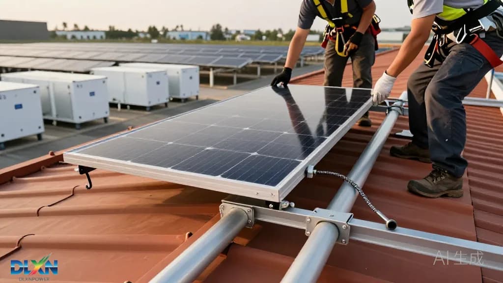
Mechanical design is governed by wind uplift, not dead load. A rail-based pitched-roof system adds 10–15 kg/m², well within the capacity of a code-compliant roof; the governing case is negative pressure at roof edges and corners, where ASCE 7-22 or EN 1991-1-4 can specify uplift coefficients two to three times the field-of-roof value. Edge zones — typically the outer 10% of the roof dimension — therefore require closer rail spacing and additional anchors, a detail routinely omitted in low-cost installations and a leading cause of panel loss in storm events.
Flashing quality determines watertightness over decades. Every penetration should use a flashed mount sealed under the course above, never surface-mounted sealant. On flat roofs, ballasted systems avoid penetrations but impose 60–120 kg/m² of load and require wind-deflection analysis plus a verified membrane protection layer. Ground mounts and elevated structures demand galvanised or mill-finish aluminium and hot-dip galvanised steel, with a corrosion category matched to site exposure — C4 for coastal installations within 1 km of saltwater.
Racking must also preserve module thermal performance. Flush mounting with less than 100 mm rear clearance can push cell temperatures 25–30 K above ambient, costing 8–10% of output at peak. Elevated tilt frames and open-ground structures restore convection. Where the site has no roof at all, dedicated structures such as the [solar sunflower](/solar-sunflower) provide a dual-axis or fixed-tilt platform with integrated cable management and pre-engineered foundations.
Inverters and the Electrical Balance of System
Inverter topology drives both yield and serviceability. String inverters offer the lowest cost per watt and 97–98.5% CEC-weighted efficiency, but a single shaded or failed module can compromise an entire MPPT channel. Module-level electronics — microinverters or DC optimisers — recover 3–8% in partially shaded installations and provide per-module monitoring and rapid shutdown compliance, at 15–25% higher balance-of-system cost. DC/AC oversizing ratios of 1.2–1.3 are now standard practice, accepting modest clipping in exchange for higher full-load hours across the year.
Wiring design follows voltage-drop and safety rules simultaneously. Keep DC voltage drop below 2% and AC below 3%; on a 40 m DC run at 12 A, that constraint frequently dictates 6 mm² rather than 4 mm² cable. String cable must be UV-rated, double-insulated and mechanically protected, with positive and negative conductors routed together to minimise induced loop area. Ground-fault protection, arc-fault circuit interruption (AFCI) and rapid shutdown to NEC 690.12 — or the equivalent national regime — are mandatory, not optional.
Surge protection is the cheapest insurance in the system. Install Type 2 SPDs at the DC combiner and at the AC distribution board, and Type 1 where a lightning protection system exists. Review MPPT windows, grid-support functions and monitoring interfaces across the [inverter technology pages](/tech/inverters), and confirm the unit's country grid code is pre-loaded — an incorrect grid profile is one of the most common causes of failed utility inspection.
Storage Integration and Backup Circuitry
Coupling architecture determines retrofit flexibility. AC-coupled storage — a battery inverter behind the PV inverter — retrofits cleanly to existing systems and simplifies grid interconnection, but incurs double conversion losses of 5–8%. DC-coupled systems charge directly from the array, achieving 88–92% round-trip efficiency, and are the logical choice for new-build installations where the hybrid inverter is specified from the outset. Review hybrid topologies and charge-control strategies in the [battery storage section](/tech/battery-storage) before committing.
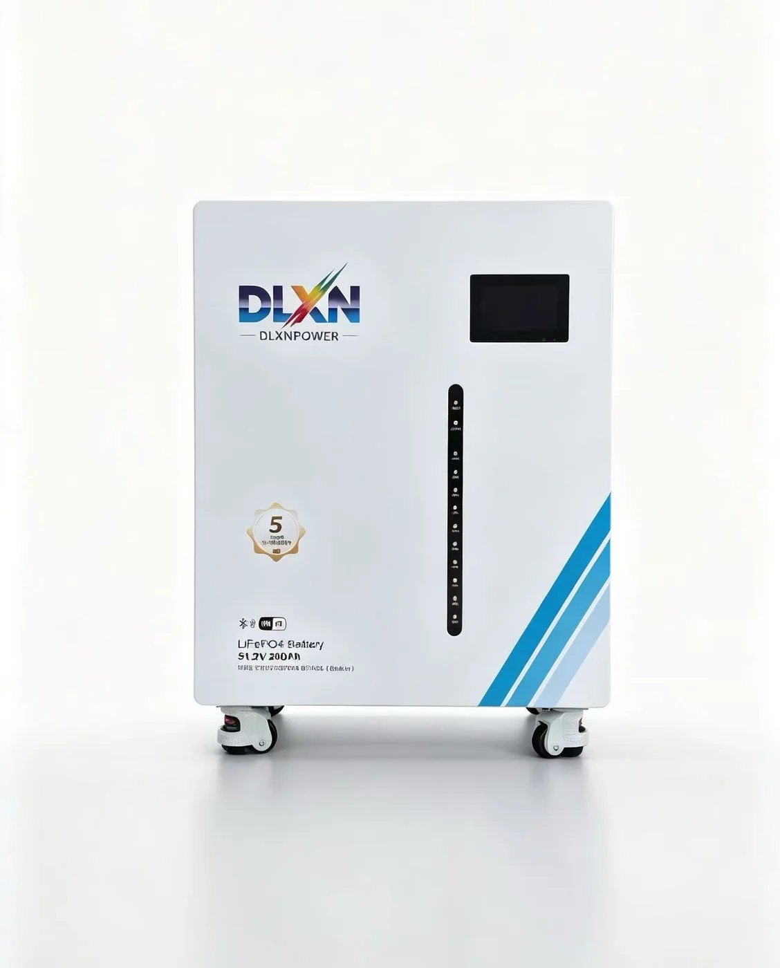
Capacity sizing should be driven by load, not by array size. A typical energy-shifting application needs 1.0–1.5 kWh of usable capacity per kWp of array; a true backup application instead requires the critical-load panel to be enumerated and autonomy defined — usually 8–12 hours for refrigeration, communications and lighting. LFP chemistry, at 6,000 cycles to 80% depth of discharge, now dominates residential and C&I deployment; verify the datasheet's cycle count, C-rate and operating temperature window across the [lithium battery range](/products/lithium-battery).
Electrical integration requires a dedicated backup sub-panel, a listed transfer mechanism, and careful neutral/ground bonding in backup mode. Size the battery inverter for surge loads — a 3 kW well pump can draw 9 kW for two seconds — and set state-of-charge limits (typically 10% floor, 95% ceiling) to protect cycle life. Commissioning must include a full island-mode transfer test under load, not merely a firmware flag.
Commissioning, Grid Connection and Handover
Commissioning is a documented, standards-based process. IEC 62446-1 defines the minimum: protective conductor continuity, insulation resistance measured at 1,000 V DC (a healthy array reads above 1 MΩ; below 40 MΩ warrants investigation on large arrays), polarity verification, open-circuit voltage and short-circuit current per string against modelled values, and functional testing of AFCI, RCD and rapid shutdown. Add I-V curve tracing at the string level and infrared thermography at 60–70% irradiance to catch cell-level defects and loose terminations invisible to a multimeter.
Grid connection involves the utility's protection settings, anti-islanding test and metering configuration. Verify the inverter's grid profile, confirm export limitation if applicable, and record the settings in the handover pack. Post-commissioning, compare the first full month's specific yield against the model: a deviation above 10% typically indicates a commissioning fault, soiling, or an incorrect irradiance assumption rather than weather. Reference installations in the [project portfolio](/projects) illustrate typical measured performance ratios for comparable designs.
Handover documentation should include as-built single-line diagrams, string layout maps, IV traces, insulation test records, module and inverter serials mapped to positions, and a monitoring login. Set a 12-month review to re-validate performance ratio and schedule first cleaning. According to NREL's cost benchmarking, balance-of-system and installation labour now represent well over half of residential system cost — which means the difference between a 0.78 and a 0.84 performance ratio is decided almost entirely by the quality of the work described above.